http://www.wa2ise.com/radios/12ba7.html
Increasing sensitivity of ordinary AA5 radios
Using the 12BA7 pentagrid converter to
replace the 12BE6 in AA5 radios
Get about 6dB more sensitivity
Or replace the 12SA7 with the 12BA7
Try replacing a 6SA7 with a 6SB7-Y, twice the conversion transconductance, same pinout.
No tuned circuit tweaking should be needed.
Using a 6BS7-Y in an AA5 to replace the 12SA7.
Try replacing the 12SK7 with a 12SG7, similar pinout, twice the gain.
May not work or be stable in all radios.
Also replace the 12BA6 with a 19HR6 for about 4dB more IF gain
Use a longer loopstick or larger loop antenna for some more signal gain
Using a 6AS6 dual control pentode for more AVC action in the IF strip.
And another 6AS6 as a mixer.
Use a 12BE6 or 12SA7 as an AVC gain controlled audio driver in place of a 12AV6 or 12SQ7
Lower heater voltage on a diode detector tube for better fidelity
Modify the IF transformers and squeeze a few more dBs of signal strength from your AA5. For experts only, practice on spare transformers first!
Improve the signal to noise performance of ferrite rod antennas
Using car radio space charge tubes in AA5 type radios, three sets, 1st with low voltage RF and IF.
Second set uses a 12VDC B+ audio output tube stage The 3rd using push pull 12K5s.
Judging the success of a modification: Basically, I want the radio to receive "real" signals and not produce internally generated interference such as "birdies" and "roaring" or "rushing" kinds of noise. Also, the radio should be able to handle strong stations without distortion. I see such problems as needing more work to produce a satisfactory mod. The mods on this page have been tested for good performance. But success can vary from one model of AA5 type radio to the next, as lead dress and board layout, and minor circuit design variations can impact modification efforts. When you do attempt a mod, be sure you can revert to the original state of things, in case results are poor. As to why these various tricks were not designed in by the manufacturer, cost was the major reason in a mass produced product like the AA5 radio.

Diagram of radio using the 12BA7 socket adapter:

I tested this 12BA7 converter tube mod in four different AA5 AM tube radios, and had no problem with unstable oscillations or tweets or birdies. And signal gain went up in all those cases. It was not really effective in an AA6 (an AA5 with RF stage) though. Because the RF stage provides enough gain to cause the AVC always to cut in. But the 12BA7 works well in the standard AA5 radio.
I built an adapter socket going from the 7 pin 12BE6 basing to the 12BA7 9 pin basing. This makes the radio easily restorable back to the 12BE6 if desired. The following cross-connections were done: (7 pin socket pin) to (9 pin socket pin(s)), 1 to 2; 2 to 3, 6; 3 to 4; 4 to 5; 5 to 9; 6 to 1, 8; 7 to 7. Keep the lead lengths as short as possible. Several of the lugs on the 7 pin socket will line up and directly connect with several of the 9 pin socket, to make a short and tight mechanical structure. This connects all the similar types of electrodes the same way as in the original AA5 circuit. The 12BA7 has an extra function, an internal shield (pin 8). I connected this to the B+ line, 7 pin socket pin 6, as this line is at RF ground potential. It's just a small piece of metal interspaced between the plate and grid 3 (the signal input) leads inside the bottom of the tube. So, the DC potential has no effect. I also connected a short length of insulated wire to this RF "ground" and placed this wire into the center space holes of both the male and female sockets, to act as additional interlead shielding. This is similar, with respect to RF, to the grounded center of tube sockets. If you decide to replace the 7 pin tube socket on the chassis or circuit board with a 9 pin socket, you should connect pins 6 (screen grid) and pin 8 (internal shield) to ground. See here. Other connections are as above. But do this only after you are satisfied that the adapter scheme yields good results.
 Finding a male 7 pin tube type socket will probably be difficult. I took a molded female socket and removed the contacts. And then I soldered an inch or so length of solid 18 gauge (AWG) copper wire to the part of the contact that usually grabs the tube's pin. This thickness of wire is very close to the same size as tube pins. Did 7 of these and reassembled the socket, now a male.
Now, time to test the mod. Be sure you have physical room for the adapter and 12BA7 next to the tuning cap (and you can tune), and inside the radio cabinet. The 12BA7 without adapter is as tall as a 50C5. The low end of the AM MW broadcast band should tune as it did before. The high end of the band may be off calibration something like 50KHz, the top (1600) now not reachable. Tweak the tuning cap's oscillator section trimmer to bring 1600 back again (backing the screw looser should do it). once you get the stations about where they belong on the dial, tweak up the antenna section trimmer of the tuning cap. Best tracking is usually had if you tweak up on a weak station near 1400KHz.
Replacing the 12SA7 with the 12BA7: 

One could instead use a 12BZ6 for the 12BA6 but the cathode and suppressor (G3) grid pins are swapped. And the 12BZ6 will need a tube shield (grounded with respect to RF) to work. I have had success with the 12BZ6, but the 19HR6 is easier and less expensive.
You may need to retune the IF some to achieve good sensitivity and stability. one thing to check for is good sound quality on strong stations. To be sure that the IF stage isn't overloading, and is driving the detector stage properly. This 19HR6 mod shouldn't be too hard for beginners, try it on a radio you don't care too much about first. This mod is less likely to yield much benefit in receivers with RF stages and multiple IF stages, though. These sets already have lots of gain, and the AVC will just assert itself more often with a mod.


.
Replacing the 12SK7 with the 12SG7 pentode in AA5 IF strips.
The 12SG7 is a semi-remote cutoff pentode with almost twice the transconductance of the 12SK7. 4100 mhos vs 2350 mhos, respectively, at plate voltage of 100V. And the plate resistance of the 'SG7 is twice that of the 'SK7, 250K vs 120K, respectively. Up to 6dB additional gain (assuming no AGC action) is possible. only drawback is that the 'SG7 has a picofarad more capacitance on the input grid than the 'SK7, so the input IF transformer may need a little tweaking. Also, the 'SG7 cathode and suppressor grid pins are connected together internally. This will cause any resistor for the 12SK7 cathode to be jumpered out, if the 12SK7 suppressor grid pin is tied directly to ground. This might cause instabilities such as "birdies" and oscillations to occur. But this tube substitution is easily tried, tune in weak stations and see if you have any problems, before you tweak the IF. The 12SG7 can also work well in place of the 12SK7 in the RF stage of six tube AM radios, like the GE model 422. Again, check for birdies and instabilities on weaker stations, and also check strong stations for distortion. Tweaking the antenna trimmer cap when tuning the high end of the band should be all you need do.
Using a 12BE6, 26D6, 18FX6 or 12SA7 as an AVC gain controlled audio driver in an AA5 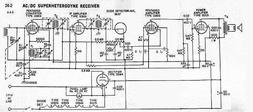
The purpose of this is to give more uniform audio volume out of the speaker when tuning across the dial from strong to weak stations. This can put those leftover 12BE6s and 12SA7s from above to use.
This mod involves using a 12BE6 with the audio input from the pot injected via cap with resistor to ground into the G1 (grid that usually does the local oscillator, it's sharp cutoff) and AVC applied to G3 to vary the gain. Thus this tube is being used as a dual control device. The audio input waveform will not suffer distortion because it doesn't see a remote cutoff grid curve over its voltage range. Grid 1 amplifies linearly the audio and it is for grid 3 that determines how many of the electrons representing this amplified audio signal get to the plate. What amount of audio electrons that don't reach the plate are diverted by grid 3 to grid 2. This diversion of the audio doesn't introduce distortion into the audio. Grids 4 and 5 just look like the screen and suppressor grids respectively in an ordinary pentode. Audio out on plate is coupled to the 50C5. Note that this audio stage resides outside the AVC feedback loop. "Forward AGC" it is called. The secret to getting enough drive and clarity to drive the 50C5 is how to bias grids 2 and 4 (screens). Used a 100K from B+ to G2 and G4, bypassed to ground with a 0.1uF cap. The voltage there is around 12 to 20V. Plenty of gain now. B+ is 95V. Same plate load as the 12AV6 had, 470K. G1 sees the same 6 to 8 megs as the 12AV6 did, develops about the same "contact" bias voltage of about -1V. only problem is distortion if the AVC goes beyond about -4V. You could use a voltage divider and another filter cap here.


As seen in the above curves for the 12BE6, the screen voltages I have actually make sense. The plate is running around 100uA, similar to what the 12AV6 used to. The screens are running at about 700uA at around 10V. Grid 1 has the curves of an ordinary triode with a sharp cutoff characteristic, and that the -1v grid bias is about right. Here the "triode" would see grid 2 as its plate. And you can see the plate current diversion to the screens caused by grid 3 (the amount of current would be scaled back by the lower screen voltage). Conversion transconductance is not meaningful here.
For comparison of the 12BE6 grid 1 "triode" with the 12AV6, here's its curves with the usual operating area in yellow:
If you have 12BE6's coming out of your ears, you can use one in the IF amp stage. Disconnect pin 7, and pin 7 now goes to the AVC line. The other pins will likely need no changes. The new tube will probably need a shield. This tube is acting similarly to the audio 12BE6, except G1 also gets some AVC action here like that seen in a sharp cutoff pentode. With enough switching, one might be able to make use of the AM 12BE6 found in many AM/FM radios as an FM IF stage like the AM IF stage described here. 
Of course you'll need a detector of some sort in the radio now that the 12AV6 is gone. Maybe the infinite impedance detector. Or use a separate diode, like an EA76 or 5647. You can reduce the contact potential by reducing the heater voltage down from 6.3 to 4 volts. In a series string, that can be done by paralleling a 100 ohm resistor with the heater. This should increase the fidelity of AM detection. The 5896 below is a dual diode version.

A longer ferrite loopstick will capture more signal out of the air. If you have the space, try making a longer one out of a pair of shorter sticks. Save the original loopstick with its coil intact so if you are not satisfied with the results, you can restore the radio back to it. Clean and epoxy the two new sticks end to end. You could even use a whole bunch of ferrite beads to make a rod. You need to use beads that are effective in the MW AM band. Try the beads out by stringing them on nonconductive string to create a rod's length as a test. Continue the below before you epoxy them together. Using one of the coilforms from one of the new sticks (remove the extra and toss into your junk box), connect it to the radio's antenna circuit. Be sure you can slide it on the stick. Tune a strong station near the low frequency end of the dial while sliding the coilform around the end of the stick. The extra amount of ferrite rod will increase the inductance, and sliding the coilform off the end will counter this. once you get a peak, try a weaker station. If you get oscillation, you may be tuning in the IF frequency, thus too much inductance. once you see how far off the end of the rod the coil now peaks at, you can start stripping turns that extend beyond the end of the stick off the coilform. And a few more. Ideally, you just want enough turns so the coil will peak resonate at around the 2/3 position along its length. The radio should be more sensitive now. Check that strong stations are not distorted or causing intermod in the band. 
A larger loop antenna can also be done. 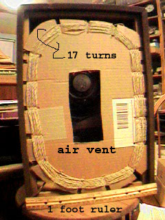 I just made an antenna for a radio I installed into an old bookshelf speaker (not a good one, so don't worry). I made it large to capture more signal out of the air. What to do: Get a spool of wire about a hundred feet long. Select wire without solder coating on it. Skin effect would force most of the RF current thru the solder, which has a higher resistance than copper, and that will kill the Q. Better yet if you have a supply of silver coated wire, usually done with Teflon wire (Teflon does bad things to copper, so the silver plating). Silver is a better conductor than copper, but as silver is much more expensive, everyone uses copper to wire their houses. Or use litz wire for the antenna if you happen to have some. Anyway, get some corrugated cardboard from that box your latest ebay win came in, and make a coil form. Cut an odd number of notches one every 2 inches or so. You will wind the wire in a basket weave pattern. This basket wave pattern needs the odd number of notches or else it won't work out. That reduces stray interwinding capacitance. You have seen this done in older AA5 antennas. I made one about 15 inches by 11 inches. It took about 17 turns. But be prepared to add or remove turns or fractions thereof. Smaller size loops will need more turns. Tune the radio the antenna is for to a weak station near the bottom of the band, like 570KHz. Connect the inner wire of your antenna to the "hot" part of the antenna tuning cap, and the outer wire to the AVC "RF ground". Use a high impedance voltmeter to monitor the AVC voltage. Add or remove turns of wire from your antenna to peak the signal strength of that station selected above. A few solder joints in the antenna won't hurt anything as long as you can't get shorted turns. You can have a few feet of wire between the antenna and AVC line as you're tweaking the antenna. You are actually adjusting the antenna inductance to resonate it to the tuning cap. After you get the peak, tune up to a station around 1500KHz and tweak the antenna trimmer cap. If you did the basket weave pattern, you should be able to get a peak. The radio should be more sensitive now. Check that strong stations are not distorted or causing intermod in the band. Now you're done.

Expect to loose 6dB of signal, and hopefully more than 6dB of noise. You'll need to tweak the antenna trimmer to compensate for whatever stray capacitance was added by the shield. With the other tricks on this page, that signal loss shouldn't be a problem.
Using a 6AS6 dual control pentode in the IF strip, more AVC control.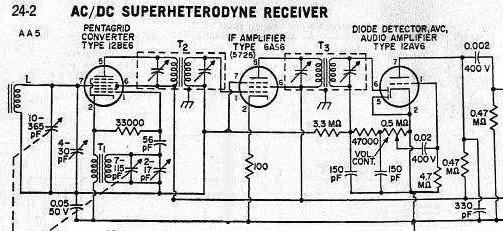
Here a 6AS6 (aka 5725) tube is used in place of the 12BA6. The 6AS6 is a dual control pentode, which means that grid 1 and grid 3 are both independent control grids. The pinout is the same EXCEPT the cathode and grid 3 are swapped. I tied the cathode to ground via a 100 ohm resistor, and grid three tied directly to the AVC line. Grid 1 goes to the IF signal lead, which also has the AVC voltage superimposed on it (this gives us extra AVC action on strong signals that yield more than -2V of AVC, see curves just below; actually this may cause "modulation rise" distortion if we use it in the IF stage, but would be good for the RF stage tube in an AA6 set, as signals are far smaller there and suffer little distortion). As the control actions on both control grids are essentially multiplied together to yield the final gain of the plate circuit of the tube, this creates a variable gain action of the IF signal, thus AVC. *There is a drawback in that if the signal is distorted because of too much gain from G1, G3 gain reduction is too late to fix it.* 

Data sheet for the 6AS6.
An interesting aspect of dual control pentodes is that the plate resistance increases in value as grid 3 is made more negative. This will load the output IF transformer's LC circuit less, causing its bandwidth to narrow. This will make for wider bandwidth on weak signals (and thus higher demodulated audio frequency response), as these signals will drive the AVC (and thus grid 3) less negative than strong stations would. But narrower bandwidth on strong signals. This is not a feature, as weak signals will be nosier, and lower audio frequency response would be desirable. Backwards to what I was hoping for. :-)
One could add a triode plate to the primary of the IF transformer to variably load the transformer and thus vary its bandwidth. This mod assumes that the IF transformers are not overcoupled, as usually the case in AA5 radios. one would need the inverse of the usual AVC voltage to feed its grid. When one increases the current thru the triode, its plate resistance decreases. We want a triode that has a rated plate resistance around 20 to 40K, like a 12AT7. We want that to happen on strong stations to get better high frequency audio fidelity. I used a zener to provide a constant bias for the cathode. Use a quiescent current resistor to keep the zener functioning when the triode passes very low current. So one needs a DC signal that gets more positive with more signal strength, so we can control the triode with it. One could get that using an infinite impedance detector instead of the usual detector diode. An interesting side effect of this triode circuit is that it also attenuates strong signals more than weak signals, thus helping the usual AVC circuit function. one has to be careful to balance things so it doesn't hog too much of this function. The diagram shows it hanging on the first IF primary, but an additional triode on the primary of the 2nd IF should also work if the detector is an infinite impedance type. The usual diode loads the 2nd IF enough such that a triode on that one wouldn't do much. That might even do enough AVC action so that the regular AVC circuit could be eliminated, but I haven't yet tried this. There may be unwanted feedback when using both triodes on a 12AT7 as both plates are not shielded from each other.
This scheme would be too expensive to build into consumer AA5's back during AA5 production.

Now back to the 6AS6 circuits....
The heater specs out 6.3V @ 175ma, but the tube didn't seem to mind at all being in a 150ma heater string. The cathode lighted up about as bright as cathodes should be, and the voltage measured about 5.9V.
6AS6 mixer
Here the 12BE6 converter tube is replaced by another 6AS6 (5725) as a mixer, and a 5977 triode as a local oscillator. This triode has a mu similar to that of the oscillator portion of the 12BE6, about 18. Its output is applied to the second control grid (G3) of the mixer 5725. This creates heterodyning action, RF * LO, which yields with other things the IF frequency. Using the AVC bias on the RF input causes a small amount of gain change on the mixer tube. This can be seen by looking at the below diagram. Sharp cutoff pentodes have a constant slope for much of their characteristic curve, but make the control grid negative enough, and you will leave the linear region and get a change in slope. High values of AVC voltage will bias the tube far enough into this changed slope area to cause gain reduction. The RF signal itself is small enough not to suffer significant distortion.  Even sharp cutoff pentodes have some remoteness.
USING 12V B+ SPACE CHARGE CAR RADIO TUBES IN AN AA5:
If you want to, you can use those 12V B+ space charge tubes intended for auto radios for the RF converter and IF sections of an AA5. No real advantage to, other than for the fun of doing it. The 12AD6 is a pentagrid converter, the 12AC6 a reasonably sharp cutoff pentode. The 12EK6and 12AF6 are somewhat remote cutoff pentodes. The 'EK is higher gain. All these pentodes can be used in the IF amplifier, though for better AVC action, the remote cutoff ones are better. All these are pin compatible with their usual AA5 counterparts. There appears to be no problem using the series string AC current to heat these tubes, even though these tubes were intended for use in 12V DC car radios. Note that one needs to add a 39K 1/2 watt resistor to drop the B+ fed to the 12AD6 and 12AC6 tubes. And a bypass cap of around 30uF. An alternative, shown in the diagram below, shows how to get the low voltage B+ from the audio output tube's cathode. Normally, the 50C5 has about 6 to 7 volts on its cathode (cathode resistor bias). This can be doubled by attaching a resistor the same ohmage as the grid to ground resistor (about 500K) from the control grid (G1) to the cathode. This creates a voltage divider with the existing grid to ground resistor so the tube will pull enough current thru the cathode resistor to make the grid 6 to 7 volts lower than the cathode. And the cathode will find itself twice the grid voltage to ground. To keep the cathode current to be similar to what it was before, I increased the cathode resistor from 150 to 330 Ohms. Be sure to use the 30uf cap mentioned before to bypass the cathode. Also, I found that I needed to change the AVC filter cap from 0.05uf to 0.22uf to reduce hum pickup. If the radio's ground happens to be connected to the hot side of the powerline, hum would come from being coupled from the outside world capacitively. A 60Hz hum signal that would modulate the RF and IF stages, which would cause variable hum on the detected audio signal. I tested this on an otherwise boring common AA5, and it did work. 
A tube radio with a "power" output stage operating from 12VDC B+
A variation of the above radio. This radio uses low voltage car radio tubes for the RF, IF, detector and first audio driver, and output stage. The 1st audio driver stage uses a bit of negative bias voltage developed by the converter local oscillator circuit. This bias voltage is about -1. 3V DC. In this set, this voltage didn't vary with tuning from one end of the band to the other. A 4.7 meg resistor is mounted next to the oscillator circuit to avoid detuning the oscillator LC tank. Small amounts of stray capacitance on the audio side of this resistor filter out the RF of the local oscillator. This resistor, in combination with the resistance to ground, provides the biasing to the grid of the 1st audio tube. You may have to select a somewhat different value to get good audio. The tube used here is another 12V tube, the 12AE6.
The amount of audio output power isn't much, about 50mW. Similar to that of a transistor radio. The output tube is a space charge tetrode, a12K5. Except for pin 5, it will fit the same socket connections as a 50C5. Pin 2 is the control grid, and pins 5 and 6 of the 12K5 are the space charge grid, which connects to B+. This tube was intended for output stage transistor driver circuits in car radios. Output transformer T4 has about a 7:1 turns ratio with an 8 ohm speaker as load. Thus the primary impedance is about 500 ohms. An output transformer from a pocket transistor radio is like this, and could be used here. Use the entire primary winding. This is similar to the load impedance this tube saw in car radios. This radio isn't exactly a boom-box :-). Maybe if you use headphones, this radio could be a vacuum tube Walkman! If you don't mind the use of a very big battery to power it (heater current is around 1 Amp.). 


For reference, a standard AA5 radio circuit:
An "instant on" AM radio using all tubes and no selenium or other solid state devices:
This is more of a "What if" type project than a practical mod. So "What if it is desired to build an instant on AM radio using only tubes and no selenium rectifier (because selenium rectifiers were never invented)?" "And no using any power on heaters while the set is "off". 
Portable tube radios power up quickly enough to be considered "instant on" because they use directly heated cathode tubes. So, using a directly heated rectifier tube for off line operation would also be "instant on" (instant being within 5 or so seconds). A 5W4 tube would be good here, as current demands are not very high. And has relatively low heater current compared to other tubes like the 5U4. But how to power the heater? one solution would be a small 5V transformer (which could be an extra winding on the clock motor if this radio is a clock radio). Another solution would be a series capacitor to the powerline. This puts a restriction on where in the circuit to install the rectifier, as cathodes of rectifier circuits are not usually directly connected to the line. If you use the rectifier to supply negative voltage instead of the more usual positive voltage, the problem of how to supply power to the heater via series capacitor goes away. Pass heater current from one side of the line thru the heater and then thru the series cap to the other side of the powerline. The only place the heater cathode is not on the "wrong" side of the tube is using it to rectify a negative supply. The B+ of the set is directly connected thru a small resistance to the line, and the negative "ground" is supplied by the rectifier tube.
Center city and factory areas: 10- 50 mv/m
residential suburbs: 2- 10 mv/m
Rural areas: 0. 1- 1. 0 mv/m
Sky wave DX from out-of-town: >0. 5mv/m 50% of the time
mv/m is the field strength in Milli Volts per Meter. An approximate formula for the Voltage induced in a "small" air loop is as follows:
E = 2 * pi * e * N * A / L
where
E = Resultant Voltage acting around the loop
e = strength of radio wave, Volts per m (normal to plane of loop)
N = number of turns in loop
A = loop area in square meters
L = wavelength of radio wave, m
Note that when the field strength is given in mv/m, it must be multiplied by 1000 to convert it to Volts/Meter as used by the loop formula.
(from a post by John Byrns)
(eom)
'진공관 라디오' 카테고리의 다른 글
| [스크랩] 대인의 과학 진공관 라디오 회로도 (0) | 2016.01.14 |
|---|---|
| AA5란 (0) | 2016.01.10 |
| 5678 진공관 라디오 회로 (0) | 2016.01.09 |
| (중국) 6J1 초재생 FM 외음축 (0) | 2016.01.04 |
| [스크랩] 12AT7 VHF 2BAND 라디오 (초재생식)....2 (0) | 2016.01.04 |